 Audio version
Listen to this article on YouTube
Watch the GoBioEng audio article with narration.
Open
Audio version
Listen to this article on YouTube
Watch the GoBioEng audio article with narration.
Open
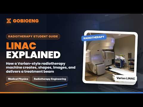
A Varian-style medical linear accelerator, or LINAC, is a treatment machine used in external beam radiotherapy. It accelerates electrons, produces and shapes radiation beams, verifies patient position, and delivers a planned dose to a target while reducing dose to healthy tissue as much as possible.

One machine, many synchronized systems
To the patient it looks like a rotating treatment machine. To the department it is a beam generator, imaging platform, mechanical positioning system, safety system, oncology software endpoint, and quality-assured clinical device working together.
- Clinical view: patient setup, image guidance, beam delivery, and treatment record must agree.
- Engineering view: RF power, cooling, vacuum, motion control, interlocks, and software all affect uptime.
- Student view: learn the LINAC as a system, not as isolated part names.
1. The Basic Principle
In photon radiotherapy, the machine generates high-energy electrons, accelerates them through an evacuated accelerating structure, and directs them toward a heavy metal target. When the electrons hit the target, X-rays are produced. These X-rays are then shaped by jaws and the multi-leaf collimator before reaching the patient.
In electron treatment mode, used on some machines, electrons can be delivered more directly for superficial targets after the target is moved out of the beam path and the beam is spread and collimated with components such as scattering foils, scanning magnets, and electron applicators depending on the design. Not every modern platform is built around the same clinical modes, so students should always separate the general LINAC principle from the exact model configuration.
2. Accelerator Physics in Simple Engineering Terms
A linear accelerator uses radiofrequency electric fields to add energy to charged particles as they travel through an evacuated accelerating structure. The key idea is timing: electrons must arrive at accelerating gaps when the electric field is in the correct direction. Because electrons become relativistic quickly, later acceleration mainly increases energy rather than speed.
The accelerator structure must be under vacuum so electrons do not lose energy through collisions with air molecules. RF cavities or waveguide sections transfer microwave energy to the electron bunches. Steering and focusing coils help keep the pencil beam aligned close to the intended axis before it reaches the bending magnet and treatment head.
| Subsystem | Engineering function | Clinical reason it matters |
|---|---|---|
| Electron gun | Produces electron bunches injected into the accelerating structure. | Beam stability starts with consistent electron injection. |
| RF system | Provides microwave power through a magnetron or klystron-based design depending on platform. | RF instability can affect beam energy, output, and machine faults. |
| Waveguide | Accelerates electrons in a vacuum using RF electromagnetic fields. | Energy consistency is essential for planned depth-dose behavior. |
| Bending magnet | In many conventional designs, bends and focuses the accelerated electron pencil beam toward the target or electron treatment path. Because different electron energies follow slightly different paths in a magnetic field, energy-selection slits or beam transport geometry can also reject off-energy electrons. | Supports correct beam energy, focal spot position, target or scattering foil alignment, field symmetry, and depth-dose behaviour. |
| Ion chambers | Monitor dose, dose rate, symmetry, and flatness-related signals. | They support beam termination and treatment delivery safety. |
MV photons and MeV electrons
Students often mix up beam labels. Photon beams are usually named in MV, such as 6 MV or 10 MV, while clinical electron beams are usually named by electron energy in MeV. The exact available energies and modes depend on the machine model, installed options, commissioning, and local clinical practice.
3. How a Patient Sees the Machine
The patient usually sees a large rotating head, a treatment couch, positioning lasers, imaging panels, and room monitors. For the patient, the most important experience is setup accuracy, comfort, communication, and confidence. They may not feel the radiation beam. The machine can move around them, make mechanical sounds, and pause while images are taken or checks are completed.
4. How Radiographers See the Machine
Radiographers see the LINAC as a treatment delivery and patient-positioning system. Their focus is daily setup, immobilization, image acquisition, matching, couch shifts, treatment delivery, patient observation, and safe communication. They work closely with physicists, oncologists, dosimetrists, and engineers when anything does not look correct.
5. How Clinicians and Physicists See It
Clinicians see the LINAC as the final delivery point of a treatment intent: target coverage, organ-at-risk sparing, fractionation, and adaptation to anatomy changes. Medical physicists see beam quality, output constancy, dosimetry, imaging accuracy, mechanical precision, safety interlocks, commissioning data, and quality assurance results.
6. How Engineers See It
Engineers see a complex electromechanical, RF, vacuum, cooling, imaging, software, and safety system. The role is not only to repair faults. It includes preventive maintenance, calibration support, fault diagnosis, parts replacement, documentation, uptime management, and escalation when patient safety or treatment accuracy could be affected.
Author's Engineering Note
A LINAC is not one machine in the simple sense. It is a synchronized treatment platform. Beam generation, mechanical motion, imaging, couch movement, interlocks, and software all need to agree before treatment can happen.
7. Main Parts of a Varian-Style LINAC
- Gantry: the rotating structure that carries the treatment head and allows beams from different angles. Some newer systems use ring-gantry style architecture rather than the older open C-arm appearance.
- Treatment head: contains beam-shaping and monitoring components such as target, flattening filter or FFF path, scattering foil or electron path components where applicable, ion chambers, jaws, and MLC.
- Couch: supports the patient and moves in controlled directions for setup and treatment positioning.
- Modulator cabinet: supplies pulsed high-voltage power for RF generation and beam production on many conventional systems.
- Accelerating waveguide: the evacuated accelerating structure where electrons gain energy from RF fields. This is different from RF transmission waveguides that carry microwave power.
- RF system: includes microwave power generation and transmission, commonly involving a magnetron or klystron depending on model and energy class.
- MLC: multi-leaf collimator that shapes the radiation field dynamically for IMRT and VMAT.
- Imaging system: kV/MV imaging, portal imaging, and CBCT tools used to verify patient position.

MLC leaves convert a beam into a treatment shape
The MLC is one reason modern radiotherapy can sculpt dose. For engineers, it means leaf motors, position feedback, calibration, interlocks, controller communication, and planned-versus-actual position accuracy. For clinicians and physicists, it directly affects target conformity and organ-at-risk sparing.
8. Gantry, Couch, and Isocenter
The gantry rotates around a fixed point called the isocenter. The treatment plan assumes the patient anatomy is aligned relative to this point. The couch moves vertically, longitudinally, laterally, and on some systems rotationally. Engineers and physicists care deeply about mechanical accuracy because small geometric errors can matter clinically.
9. Modulator, RF System, and Waveguide
The modulator creates high-voltage pulses used to power the RF generation system. RF energy is fed into the accelerating structure, where electrons are accelerated. The accelerating structure must maintain precise electromagnetic behavior and operates under vacuum. Cooling, pressure, pulse timing, RF power, and interlocks all matter.
In many conventional medical LINACs, the RF source is either a magnetron or klystron. A magnetron generates microwave power directly and is compact. A klystron amplifies RF power and is often associated with higher-energy or higher-power designs. The exact configuration varies by model, but the engineering question is always the same: can the RF chain deliver stable, repeatable energy to the accelerating structure?
The bending magnet is also more than a pipe bend. Its primary job is beam transport: bend, focus, and deliver the electron pencil beam to the correct target or electron-treatment path. Because the path of an electron in a magnetic field depends on its momentum, energy-selection geometry can also help remove electrons outside the intended energy window before they reach the target or scattering system. This is why bending magnet current, steering, symmetry, and depth-dose checks are linked in machine QA and service thinking.
10. Beam Shaping: Target, Flattening Filter, Jaws, and MLC
Jaws define a rectangular field boundary. The MLC adds fine shaping with many motorized tungsten leaves. In IMRT and VMAT, the MLC can move during treatment to modulate dose. For an engineer, MLC work involves motors, encoders, leaf calibration, communication, collision logic, and trajectory accuracy. For a physicist, it is also a dosimetric and QA concern.
In photon mode, electrons strike a high-Z target, commonly tungsten or a tungsten alloy, to create bremsstrahlung X-rays. A primary collimator limits the beam cone. A flattening filter may be used to make the beam more uniform across the field, while flattening-filter-free modes remove that component for higher dose-rate delivery in suitable techniques. Monitor chambers sample the beam before it leaves the head.
11. MV Imaging, kV Imaging, and CBCT
MV imaging uses the treatment beam energy range and can verify field placement or anatomy, but image contrast is different from diagnostic kV images. kV imaging uses lower-energy X-rays and is widely used for sharper bony anatomy visualization. CBCT rotates imaging around the patient to create volumetric images for image-guided radiotherapy.
Varian's older Clinac platforms often used add-on imaging systems such as On-Board Imager. Newer platforms integrate imaging and workflow more tightly. Halcyon and Ethos are ring-gantry style systems with a different user experience compared with older open-gantry Clinac systems. Students should not assume that a visible Clinac subsystem layout maps one-to-one onto newer enclosed platforms.
12. Machine Generations: From Clinac to Ethos
Older Clinac systems, including the Clinac 600 family and higher-energy Clinac platforms, helped establish modern external beam radiotherapy workflows. Clinac 2100 and Clinac iX-era systems expanded image guidance and advanced delivery capabilities in many clinics. Specific capabilities vary by model, energy configuration, MLC, imaging package, and local upgrades.
TrueBeam represented a more integrated platform for image-guided radiotherapy, VMAT, stereotactic work, and streamlined control of beam delivery and imaging. Halcyon moved toward simplified high-throughput image-guided treatment with a ring-gantry style design. Ethos builds on the idea of adaptive radiotherapy, where daily imaging and planning tools support adapting treatment to patient anatomy changes.

Clinac-era machines are still important for learning
Clinac machines make the LINAC architecture easier to visualize: gantry, stand, treatment head, couch, modulator cabinet, waveguide, and imaging accessories are more visibly separated than in newer ring-gantry designs.
- Open C-arm geometry helps students see gantry, couch, treatment head, and imaging panels.
- Service learning often begins by mapping visible subsystems to beam generation and safety functions.
- Newer platforms may hide more hardware behind integrated covers and workflow automation.
| Platform family | Typical learning value | What changed over time |
|---|---|---|
| Clinac 600 / older Clinac | Good for learning basic C-arm LINAC geometry and conventional treatment delivery. | Earlier workflows, simpler imaging integration, and more separate accessory systems. |
| Clinac iX / 21EX-era systems | Good bridge into IMRT, image guidance, MLC workflows, and serviceable subsystem thinking. | More advanced MLC, OBI/kV imaging options, and broader clinical treatment techniques. |
| TrueBeam | Good example of integrated high-precision treatment delivery, imaging, VMAT, and stereotactic workflows. | More unified control, faster delivery options, and tighter integration of imaging and treatment. |
| Halcyon | Good example of simplified workflow and ring-gantry style treatment experience. | Patient-centered enclosure, streamlined operation, integrated imaging, and high-throughput design. |
| Ethos | Good example of adaptive radiotherapy workflow and AI-assisted contouring/planning concepts. | Daily anatomy-driven adaptation moves planning decisions closer to the treatment session. |
13. What Students Should Remember
- A LINAC is a treatment system, not just an accelerator tube.
- Radiotherapy requires agreement between plan, patient position, imaging, beam model, and machine performance.
- Radiographers focus on setup, imaging, delivery, and patient interaction.
- Clinicians focus on treatment intent, target coverage, and normal tissue protection.
- Physicists focus on beam accuracy, commissioning, dosimetry, QA, and safety.
- Engineers focus on uptime, faults, calibration support, safety systems, and reliable machine behavior.
14. Safety and Learning Boundary
This guide is for educational understanding only. LINAC service, QA, commissioning, and clinical operation must be performed by trained authorized professionals following manufacturer documentation, hospital policy, regulatory requirements, and medical physics procedures.
Student takeaway
When studying a LINAC, do not memorize only part names. Build a system view: energy generation, beam shaping, imaging, patient positioning, QA, safety interlocks, software records, and who makes decisions at each stage.
What not to assume
Do not assume that every LINAC has the same RF source, bending magnet geometry, electron mode, flattening filter, imaging package, or service layout. Use this article as a field map, then check the exact manufacturer manual, commissioning data, and local QA procedures for the machine in front of you.