Unlike X-rays, CT, and MRI which rely on the electromagnetic spectrum, Ultrasound relies on the propagation of mechanical, longitudinal sound waves through a physical medium (human tissue). It operates in the megahertz (MHz) range, far beyond human hearing, to generate real-time, non-ionizing anatomical images.
Engineering takeaway
Ultrasound is a trade-off between penetration and resolution. Higher-frequency probes show finer detail but do not travel as deeply; lower-frequency probes penetrate deeper but sacrifice detail. Probe choice is therefore an engineering decision shaped by anatomy.
1. The Physics of Sound in Tissue
Acoustic Impedance and Reflection
Ultrasound imaging is based on pulse-echo physics. A transducer sends a short burst of sound waves into the body. As this wave travels, it encounters boundaries between different tissue types (e.g., muscle vs. fat). At these boundaries, a portion of the wave is transmitted deeper, and a portion is reflected back as an "echo."
The amount of reflection depends on the difference in Acoustic Impedance (\( Z \)) between the two tissues. Acoustic impedance is defined as:
$$ Z = \rho \times c $$
Where \( \rho \) is the physical density of the tissue (kg/m3) and \( c \) is the speed of sound in that tissue (roughly 1540 m/s for average soft tissue).
The intensity reflection coefficient (\( R \)) at the boundary between Tissue 1 and Tissue 2 is calculated as:
$$ R = \left( \frac{Z_2 - Z_1}{Z_2 + Z_1} \right)^2 $$
- Small Impedance Mismatch (Soft Tissue to Soft Tissue): \( R \) is around 1%. Most of the sound continues penetrating, allowing us to see deep structures.
- Large Impedance Mismatch (Soft Tissue to Bone): \( R \) is roughly 40-50%. A strong echo returns (appearing bright white), but very little sound penetrates the bone, creating a black "acoustic shadow" behind it.
- Massive Impedance Mismatch (Soft Tissue to Air): \( R \) is nearly 99.9%. Sound cannot pass from the transducer face (or skin) into the air. This is exactly why a sonographer must use an acoustic coupling gel to eliminate the air gap and match the impedance, allowing the sound to enter the body.
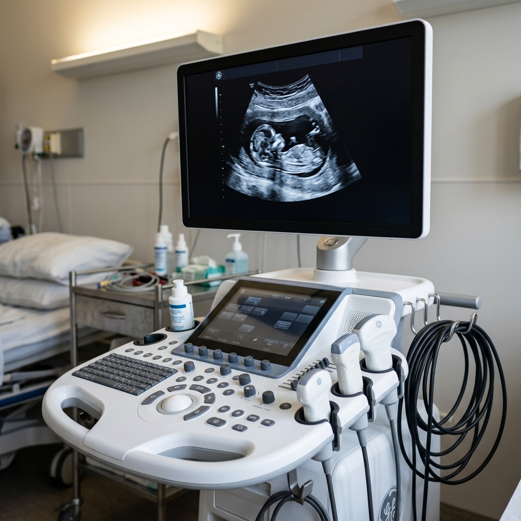
2. The Transducer: The Piezoelectric Effect
The heart of the machine is the transducer probe. Inside the plastic housing is an array of highly brittle ceramic crystals, most commonly Lead Zirconate Titanate (PZT). These crystals exhibit the Piezoelectric Effect.
Transmission (Reverse Piezoelectric Effect): When an alternating electrical voltage is applied across the PZT crystal, it rapidly expands and contracts. This mechanical vibration generates the high-frequency sound wave.
Reception (Direct Piezoelectric Effect): When the returning sound echo strikes the crystal, the physical pressure deforms the crystalline lattice, which forces electrons to shift, generating a tiny, measurable electrical voltage that is sent to the image processor.
3. Beam Steering and Phased Arrays
To create a 2D image, the sound beam must be swept across a field of view. Early machines mechanically swept a single crystal back and forth on a motor. Modern machines use pure electronic beamforming across an array of hundreds of individual PZT crystals.
In a Phased Array transducer (commonly used in echocardiography to image the heart between the ribs), all 128 (or more) crystals fire to create a single pulse. However, the machine applies microsecond electronic delays to each individual crystal.
By firing the left-most crystals slightly earlier than the right-most crystals, the resulting wavefronts constructively interfere at an angle, effectively "steering" the sound beam to the right without moving the probe physically. By rapidly changing these delays, the beam sweeps across a 90-degree sector in milliseconds.
4. The Doppler Effect and Color Flow Imaging
Beyond static anatomy, ultrasound can measure the velocity of moving blood by exploiting the Doppler Effect.
If the sound wave bounces off a red blood cell moving towards the transducer, the returning echo will have a slightly higher frequency than the transmitted wave. If the cell is moving away, the frequency is lower. The machine measures this Doppler shift (\( f_d \)):
$$ f_d = \frac{2 f_0 v \cos(\theta)}{c} $$
Where \( f_0 \) is the transmitted frequency, \( v \) is the blood velocity, \( c \) is the speed of sound, and \( \theta \) is the angle between the sound beam and the blood vessel.
- The Cosine Problem: Notice the \( \cos(\theta) \). If the sonographer holds the probe exactly perpendicular (90 degrees) to the blood vessel, \( \cos(90^\circ) = 0 \). There will be no Doppler shift detected, and the machine will falsely show zero blood flow. Proper angling is a critical clinical skill.
- Color Doppler: The machine assigns colors (typically Red for flow towards the probe, Blue for flow away) and overlays this onto the grayscale anatomical image (B-mode) in real time.
5. Real-World Engineering Problems
- Transducer Damage (The Drop): PZT crystals are brittle ceramics. When a probe is dropped on a hard hospital floor, the crystals shatter, creating "dead zones" (black vertical dropouts) on the image. Transducers are extremely expensive to replace (often $5,000 - $15,000+).
- Cable Strain: A transducer cable contains over 100 microscopic coaxial wires. It constantly gets run over by wheels, twisted, and pulled. Broken micro-coaxial cables inside the wire sheath lead to severe signal loss.
- Thermal Indices: Pumping high-frequency sound energy into tissue causes it to heat up, particularly near bone. Engineers must design machines to adhere to strict FDA thermal index (TI) safety limits, ensuring the machine automatically reduces acoustic power if the temperature rise in the tissue approaches dangerous levels (especially critical in obstetrics).
Why probe selection matters
A linear high-frequency probe suits superficial vessels and musculoskeletal imaging. A lower-frequency curvilinear probe penetrates deeper for abdominal imaging but sacrifices fine detail.
Why operator skill matters
Ultrasound is highly user-dependent. Image quality depends on probe angle, pressure, acoustic window, gain, depth, focus, Doppler angle, and anatomy knowledge.